
Configure a SPI peripheral with the Devicetree Manager
This tutorial sets up a SPI controller on an STM32 board with the Devicetree Manager for Zephyr. The example uses spi3 on a Nucleo H563ZI; the flow is the same on any STM32 board.
Before you start
Install and open the Devicetree Manager as shown in Installing the Devicetree Manager for Zephyr. If you are new to Zephyr on STM32, start with Getting started with Workbench for Zephyr.
1. Pick the SPI controller and enable it
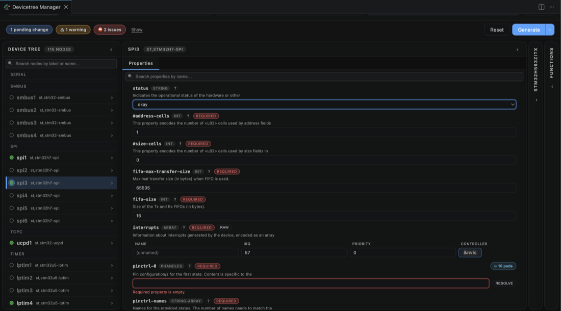
Build your application once, open the Devicetree Manager, and select the SPI controller in the device tree, here spi3. It starts disabled.

Set status to okay. The header reports that the pins are still missing.
2. Assign the signals
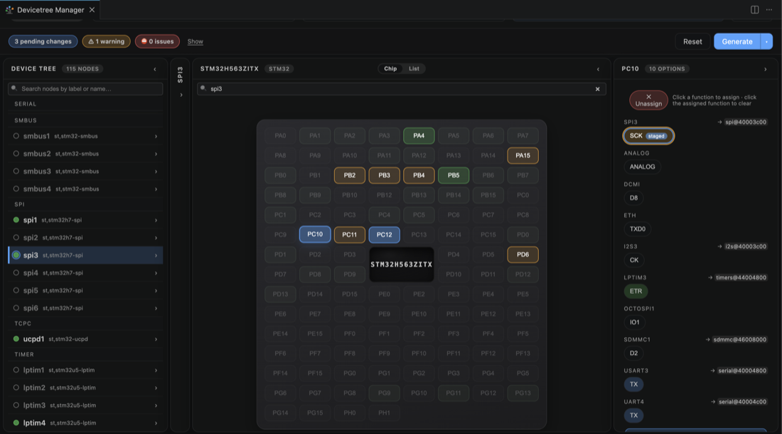
Switch to the Chip view; the pads that can carry the spi3 signals light up. Click a pad and pick its function, here SCK on PC10 and MOSI on PC12. Add MISO and a chip select the same way if your device needs them.
3. Generate the overlay
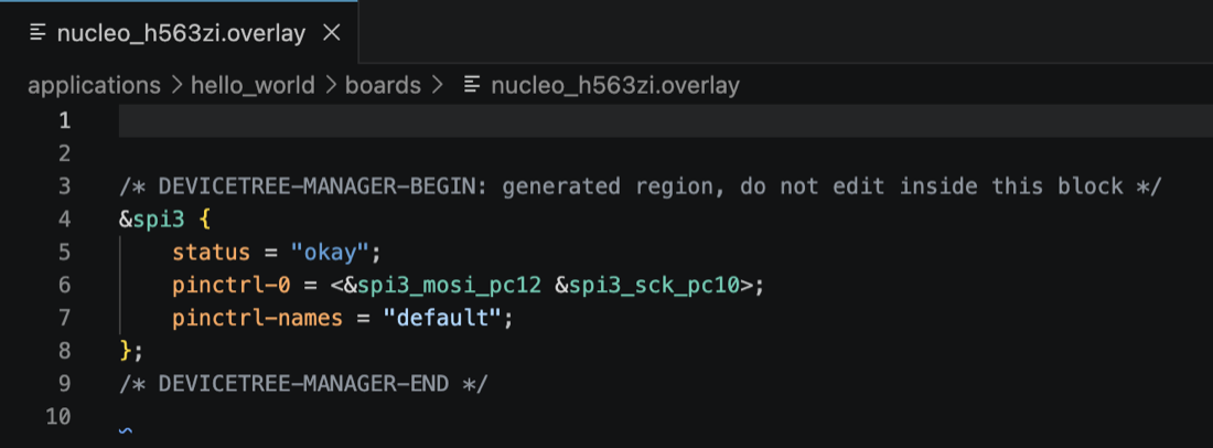
When the header reads 0 issues, click Generate to write boards/<board>.overlay, then rebuild.
-
See also: Devicetree Manager for Zephyr, Configure an I2C peripheral with the Devicetree Manager, Configure a USART with the Devicetree Manager, Configure an ADC channel with the Devicetree Manager.